How to Manage and Prevent Cohesive Bulk Solids from Clogging Industrial Chutes
Blockages in chutes are seldom flukes. Material’s cohesive strength at a high stress point overcame gravity. Yet, having no way to measure those forces, plant teams throw solutions at the stoppage and hope they stick. If you want to know exactly what’s needed and not gamble on new equipment or a different layout, you’re going to need data.
Why bulk solids stop moving in the first place
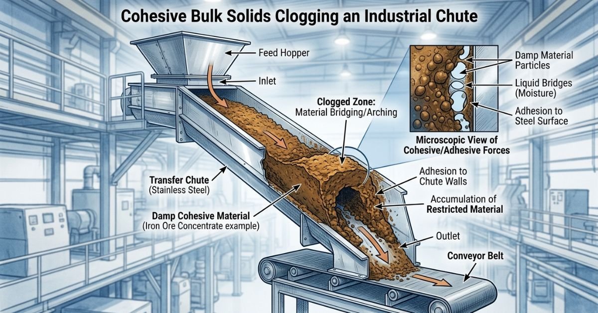
A blockage occurs when the material at an outlet has “cohesive strength” greater than the stress that gravity can produce to pull it out. The material holds together and forms a bridge. That’s all, no wizardry, no curse, just some pretty solid powder. The material has developed sufficient internal resistance to support itself like a tiny bridge across the exit, and unless something alters that structure, it simply stays put.
This is why the first thing to do is look at the transition – any place where the chute outlet cross-section shrinks. The ‘span’ is least, and a bridge is easiest to form. Looking further back along the chute body is probably a waste of time: the location of failure is almost always right at the neck.
Two distinctly different failure mechanisms are always lumped together, but treating them the same way is a common mistake:
Arching (or Bridging) is a complete stop-off. The material forms a dome over the outlet and stops flowing.
Ratholing occurs when a central hole keeps ‘teaspooning’ while stagnant material builds up on the walls. It looks as if the outlet is performing alright (Teaspooning is the term used for the erratic flow through a partially blocked outlet). Then, sooner or later, the stagnant material breaks free and bombards the outlet, which is a hazard in itself.
To unblock an arch you poke. The force has to be applied right at the bridge to break it. To control a rathole, you must reactivate the complete cross-section, not just poke the centre and increase the hole while leaving the walls undisturbed.
Cohesive strength is a material property, not a chute problem
Before anyone gets all excited about chute geometry or bolts on a flow aid, start by asking why it’s cohesive enough to arch. Cohesive strength comes from interparticle forces – fines content, moisture, surface chemistry, sometimes electrostatic effects – and it’s not a constant. It will vary with how the material was stored, how long it’s been sitting, and what the weather’s done lately.
The most dangerous hidden factor is the one that looked harmless last month. For a given material, fines fraction might double yearly under normal processes and nobody notices until they go from 10% to 30% and suddenly, “weird,” nothing flows like it used to. Fine fractions cause exponential increases in cohesion. Coarser particles aren’t just leaning on air between their neighbors – they’re leaning on a matrix of fines and making diamonds look like rake teeth by comparison.
Particle size distribution is the sleeper of the bulk solids world. For a wide size range, the smaller particles fill the voids between the larger ones; the larger particles don’t roll, they bridge on the smaller. The higher the fines fraction goes, the more your bulk material behaves like a low porosity solid. Cohesion goes through the roof, and air can’t find a way out from the rapidly consolidating bulk when you quit slinging it around.
And guess what? Fine fractions get you coming and going. Not only do they mush up the transition between your silo and silo cones or your bin walls, or pull chimney stunts in your stockpiles and conveyor galleries, but they block the air passages in your aeration pad too.
Geometry is the first lever, not the last resort
Once you’ve mastered material, geometrical fixes are lowest cost and highest durability – and here, three factors determine whether a stable arch or rathole can even form: outlet width, taper angle, and the length of any vertical section above the outlet.
Wall friction angle is the number that rules taper. Every liner-material combination has a friction angle, and the chute wall must be steeper than that angle for the material to self-clean rather than cling. This is the difference between mass flow, where the whole cross-section moves together and stagnant zones never get a chance to form, and funnel flow, where a core channel moves and material against the walls stays put – which is how you’ll get ratholing.
Practical fixes at this stage include:
- Widening the outlet past the critical arching dimension calculated from the shear test data, so the span is too wide for the material’s measured strength to bridge.
- Steepening the chute walls below the measured wall friction angle in order to convert funnel flow to mass flow.
- Swapping in low-friction liners – UHMW-PE, stainless steel, PTFE – to lower the effective friction angle without a complete rebuild.
- Adding aeration pads at points you know from experience tend to initial buildup. Aeration uses low pressure air injection to keep the material loose before it consolidates rather than to try to break an arch after the fact.
These are passive interventions. They don’t require controls, power, or scheduled maintenance cycles. They just alter the physics so the failure mode can’t get started. If a plant can afford to modify a chute, this is where the budget should go first.
When geometry can’t be changed, active flow aids take over
Most existing process chutes have seen too many bad fixes, too many better-left-forgotten designs from an engineer decades out of mind – and that means a lot of flow problems had a head start. The chute is already built, the structural steel is already in place, and re-cutting a hopper cone means a shutdown nobody wants to schedule. This is where active flow aids come into play; specifically, vibrators versus air cannons.
Vibrators use a motor to shake the wall of the chute; this can be somewhat effective at dislodging very weak, friable buildup of dry or mildly sticky product. However, the use of vibrators is related to the material cohesion, ie. it just wouldn’t have any effect on material that is cohesive enough to form a load-bearing arch of product. In such situations, mechanical vibration can actually pack the material tighter against the wall instead of breaking it loose. Vibration simply can’t produce the required force for lifting and displacing it.
Where access allows, mounting an air cannon near the arch zone converts stored compressed air into a directed pulse that shatters the bridge without stopping production. That’s a meaningfully different mechanism from vibration, and it’s why cannons succeed on materials that leave vibrators spinning their wheels.
Where you put the cannon makes all the difference. A cannon that’s too high or too low or is pointing straight down and not slightly into the direction of flow is wasted energy. It’s firing ricochets down the side wall and not toward the bridge. Inclined nozzle aiming is critical so energy goes primarily toward the bridge, not down the compaction sides of the vessel. A far more effective strategy is to install the nozzle directly into the arch zone, or have multiple nozzles positioned to cover the entire arch.
Firing sequence matters just as much as position. On multi-cannon installations, firing everything at once tends to dislodge a huge slab of consolidated material in one go, which can overload a discharge conveyor or send an avalanche into a hopper below. The better approach is sequential bottom-up bursts under PLC control, timed through solenoid valves so the bridge collapses progressively from the bottom rather than releasing all at once. It’s a more controlled failure, and it’s easier on downstream equipment.
Keeping the air supply and the structure honest
An air cannon will perform well only if it receives compressed air well. This means ample receiver volume and pressure – probably 8-10 bar worth, in addition to dried, oil-free air. Cannons can also underperform due to a supplier furnishing undersized or contaminated air lines. The cannon will fire weak exactly when the arch is hardest if they do this. Generally speaking, that is about the worst time for a soft blast.
Infrequent, if any, considerations are made regarding the wall structure of the chute into which the cannon is to be fitted. While blast loads are usually small – if the cannon’s functioning properly – the stress of multiple blasts of this type and the occasional large arch giving up all at once is anything but small. Thin-gauge sheet metal that sufficed for gravity flow alone may start cracking or denting under cannon fire for cyclic levels of a rathole blow.
Make no mistake: lock-out/tag-out is not optional on clogged chutes whether they have cannons or not. Unfortunately, the compounding factor is that a rathole that finally lets go or an arch that’s been softened by a blast can drop a substantial mass with no warning if the system isn’t isolated.
All of the above should carry ramification akin to this industrial real estimate. Improperly managed unplanned downtime has industrial manufacturers losing up to USD $260,000 an hour of it (source: Aberdeen Group), and a chute that blocks every few shifts is the epitome of an unmanaged reliability problem. A five-minute blockage that occurs twice per week may well add up to a quarter of production time, no one’s even thought of measuring the labor costs of removing it manually in those figures.
Putting the sequence together
The sequence matters more than any single fix. Solve the rathole or arching problem first, as each requires a different intervention at different locations within the chute. Determine the actual moisture and fines content in the real operating environment instead of relying on whatever was supplied with the spec sheet. Where geometry constraints allow, address the ratholing problem by creating a wider outlet, steepening the walls, or designing and fabricating more effective liners. This will eliminate the failure mode rather than just fighting it once it gets started.
When constraints dictate that the problem transfer point can’t be improved, bring in active flow aids that are scaled based on real testing of the cohesive strength, and ensure the devices are properly located and sequenced at discharge. In addition to making sure that the air supplies are adequate and cleanly plumbed to the devices, confirm that the existing structure can support the dynamic loads involved. Skip the diagnosis step and jump straight to bolting on hardware, and there’s a decent chance the fix doesn’t hold – or worse, it hides a problem that keeps getting more expensive to ignore.

Ellie Wheatley is a dedicated writer at AVTube.org who enjoys creating accurate, engaging, and easy-to-understand content. She is passionate about sharing helpful information, researching reliable sources, and delivering high-quality articles that keep readers informed and inspired.